FDTD wave equation solver
I developed a GPU accelerated finite difference time domain (FDTD) solver for the wave equation and a graphical interface to construct boundary conditions and visualize solutions in real time. The description below gives a brief introduction to the FDTD method, a practical implementation and some example systems. The solver and it’s graphical interface can be found on github.
Introduction
The wave equation is a second order PDE appearing in the description of a wide range of physical systems. It describes the propagation of disturbances (waves) in both mechanic systems and electromagnetic waves in free space.
We consider some scalar field \(u(\textbf{x}, t)\) which describes the system of interest. In a mechanical system, \(u\) might describe displacement of a solid or fluid. In electromagnetics, \(u\) might be a component of the electric field. For such a scalar system, the wave equation is
\[\nabla^2 u - \frac{1}{c^2} \frac{\partial^2 u}{\partial^2 t} = 0, \tag{1}\]where \(c\) is some positive real coefficient that may vary with space. It describes the speed of the waves in the system and is related to the properties of the media in which propagation occurs.
Our goal is to efficiently find numerical solutions to this equation subject to arbitrary boundary conditions.
FDTD
We implement the finite difference time domain (FDTD) method described by Yee [1]. The solver is implemented with OpenGL. To allow for a simple graphical interface to specify boundary conditions and media properties, we only consider 2 dimensional systems.
In order to perform numerical computations, we must discretize \(u\) in both space and time. We consider a grid with physical spacing \(\Delta x\) and timesteps \(\Delta t\). We are only interested in the value of \(u\) at these points, which we denote as
\[u_{i,j}^n = u(i\Delta x, j\Delta x, n\Delta t).\]We need a way to numerical approximate the derivatives involved in the wave equation. For the spacial derivative in the x direction, we can simply use the second symmetric derivative,
\[\frac{\partial^2 u}{\partial^2 x} = \lim_{h \to 0} \frac{u(x + h, y, t) - 2u(x, y, t) + u(x - h, y, t)}{h^2} \approx \frac{u_{i+1,j}^n - 2u_{i,j}^n + u_{i-1,j}^n}{\Delta x^2},\]with a similar result in the y direction,
\[\frac{\partial^2 u}{\partial^2 y} \approx \frac{u_{i,j+1}^n - 2u_{i,j}^n + u_{i,j-1}^n}{\Delta x^2},\]giving the combined Laplacian
\[\nabla^2 u = \frac{\partial^2 u}{\partial^2 x} + \frac{\partial^2 u}{\partial^2 y} \approx \frac{u_{i+1,j}^n + u_{i,j+1}^n - 4u_{i,j}^n + u_{i-1,j}^n + u_{i,j-1}^n}{\Delta x^2}. \tag{2}\]The time derivative in the wave equation presents more trouble. Because the simulation is performed in the time domain, we know only \(u_{i,j}^n\) for \(n < N\), where \(N\) is the current time step. We can decompose the wave equation into two coupled PDEs which are first order in time, that is,
\[\begin{align} \frac{\partial u}{\partial t} &= u', \tag{3} \\ \frac{\partial u'}{\partial t} &= c^2 \nabla^2 u. \tag{4} \end{align}\]We can approximate the first PDE \((3)\) with the limit definition as
\[u' = \lim_{h \to 0} \frac{u(x,y,t+h) - u(x,y,t)}{h} \approx \frac{u_{i,j}^{n+1} - u_{i,j}^n}{\Delta t},\]which we rearrange to yield
\[u_{i,j}^{n+1} = u_{i,j}^n + \left(\Delta t\right) u{'}_{i,j}^{n}.\]Similarly, for the second PDE \((4)\) we have
\[\frac{\partial u'}{\partial t} = \frac{u{'}_{i,j}^{n} - u{'}_{i,j}^{n-1}}{\Delta t} = c^2 \nabla^2 u.\]Rearranging, we can isolate the term for the current state of the system, \(u{'}^{n}\), and have
\[u{'}_{i,j}^{n} = u{'}_{i,j}^{n-1} + \left(\Delta t\right) c^2 \nabla^2 u.\]Combining with \((2)\), we have the system
\[\begin{align} u{'}_{i,j}^{n} &= u{'}_{i,j}^{n-1} + \frac{\Delta t}{\Delta x^2}\left(u_{i+1,j}^n + u_{i,j+1}^n - 4u_{i,j}^n + u_{i-1,j}^n + u_{i,j-1}^n\right), \tag{5}\\ u_{i,j}^{n+1} &= u_{i,j}^n + \left(\Delta t\right) u{'}_{i,j}^{n}, \tag{6}\end{align}\]which we can easily solve via iteration. We initialize \(u^2_{i,j}\) and \(u{'}^1_{i,j}\) from initial conditions. For \(n \geq 2\), each round of iteration consists of two steps:
- update \(u'\) from \((5)\), and
- update \(u\) from \((6)\) using the just computed \(u'\).
Boundary Conditions
The solver supports both Dirichlet (\(u = 0\)) and Neumann (\(\frac{\partial u}{\partial x} = 0\) or \(\frac{\partial u}{\partial y} = 0\)) boundary conditions. The Dirichlet condition can be implemented by setting \(u_{i,j}^n = 0\) at each round of iteration. The Neumann condition can be implemented by fixing \(u_{i,j}^n\) to match its appropriate neighbor—one of \(u_{i-1,j}^n\), \(u_{i+1,j}^n\), \(u_{i,j-1}^n\), or \(u_{i,j+1}^n\), depending on the orientation of the surface on which the boundary condition is imposed.
Boundary Layer
The discretization grid is bound over some finite domain \((i, j) \in [0, I] \times [0, J]\). At the edges of that domain, we cannot evaluate \((2)\) and instead have to apply some boundary condition. Ideally, we would like disturbances which reach the edge of the domain to be absorbed. Unfortunately, both the Dirichlet and Neumann boundary conditions lead to reflection rather than absorption, shown in Figure 1.
Figure 1: Wave propagation with Dirichlet boundary condition at the edge of the simulation domain. The wave reflects off the edges, creating a standing wave pattern.
One way to implement absorption is with a layer near the edge of the domain over which we damp the response of \(u\) [2]. We define a damping function
\[\sigma(d) = \tan^{-1}\left(\frac{2d}{D} + 1\right),\]where \(d\) is the distance from the edge of the domain and \(D\) is the width of the absorbing layer. The function approaches 0 near the edge of the domain. In the layer, we modify the iteration step \((6)\) to include damping,
\[u_{i,j}^{n+1} = \sigma(i,j)u_{i,j}^n + \left(\Delta t\right) u{'}_{i,j}^{n}. \tag{7}\]The damping term dissipates energy in the wave while providing a smooth impedance discontinuity to minimize reflections near the boundary.
Figure 2: Wave propagation with an absorbing boundary layer. The white lines indicate the edge of the layer. The wave is almost fully damped before reaching the edge of the simulation domain.
Implementation
The algorithm described above is implemented in a GLSL fragment shader. The shader operates on a single texture, with the following channels:
.x- \(u_{i,j}^{n}\),.y- \(u{'}_{i,j}^{n}\),.z- \(c_{i,j},\) the value of wave speed at the given point,.w- boundary conditions (0 for no condition, 1 for a Neumann condition).
The evaluation of the Laplacian follows \((2)\) and is given below.
// calculate the new u_tt value for a point based on its neighbors
float calc_wave_eq(ivec2 point, float u_point, float wave_speed) {
    // get neighbors and calculate laplacian (via second symmetric derivative)
    float u0 = get_value(ivec2(point.x - 1, point.y), u_point);
    float u1 = get_value(ivec2(point.x + 1, point.y), u_point);
    float u2 = get_value(ivec2(point.x, point.y - 1), u_point);
    float u3 = get_value(ivec2(point.x, point.y + 1), u_point);

    float laplace = (u0 + u1 + u2 + u3 - 4.0 * u_point) / (delta_x * delta_x);

    return wave_speed * wave_speed * laplace;
}
Calculation of the damping function \(\sigma(i,j)\) is given below.
// return damping factor for a point
float damping(vec2 point) {
    ivec2 tex_size = textureSize(sim_texture, 0);
    // get distance from point to closest edge
    float dist = min(min(point.x, point.y),
      min(float(tex_size.x) - point.x, float(tex_size.y) - point.y));
    if(dist < damping_area_size) {
        float norm = dist / damping_area_size;
        return tanh(2.0 * norm + 1.0);
    } else {
        return 1.0;
    }
}
The main iteration loop follows \((5)\) and \((7)\) and is given below.
void main() {
    vec4 point = texelFetch(sim_texture, ivec2(gl_FragCoord.xy), 0);
    float u = point.x;
    float u_t = point.y;
    float ior_inv = point.z; // inverse index of refraction

    float u_tt = calc_wave_eq(ivec2(gl_FragCoord.xy), u,
      ior_inv * wave_speed_vacuum);

    u_t += u_tt * delta_t;
    u_t *= damping(gl_FragCoord.xy);

    u += u_t * delta_t;

    color = vec4(u, u_t, point.b, point.a);
}
Examples
Double Slit
A plane wave incident on two small slits with a small separation demonstrates a double-slit pattern. When the plane wave passes through the slits, the resulting light diffracts, forming hemispherical wavefronts radiating from each slit. Interference between the two wavefronts creates the diffraction pattern.
Figure 3: Double slit interference.
Impedance Mismatch
A plane wave incident on two media with varying refractive indexes produces both a transmitted wave and a reflection. The extend of mismatch between the media results in a differing distribution of power between the transmitted and reflected wave. Additionally, the speed of wave propagation changes in the different media.
The circular wavefronts that appear to reflect off the corner between the three media are due to diffraction.
Figure 4: Reflection and transmission of a plane wave across an impedance mismatch. The medium in the lower left has the highest refractive index, followed by the medium in the lower right and the free space in the upper region.
Total Internal Reflection
A plane wave incident on a media at an angle greater than the Brewster angle produces total internal reflection, with little transmission.
Figure 5: Total internal reflection.
Doppler Effect
A moving source causes an apparent change in frequency along the direction of motion, the doppler effect.
Figure 6: Doppler effect with a source moving at 75% of the wave speed.
Figure 7: Shockwave created by a source moving at 200% of the wave speed.
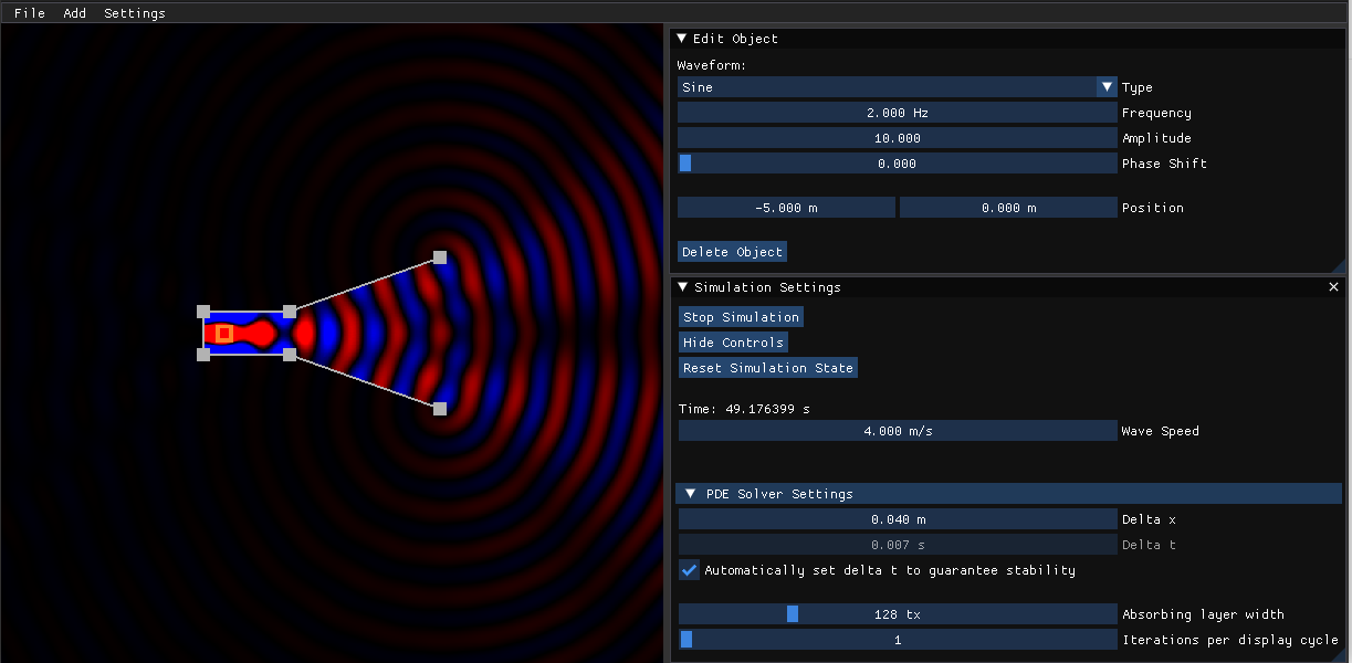
Straight vs Mitered Bends in a Waveguide
A wave encounters a bend section of waveguide, shown in Figure 6. The guide with the straight bend has a larger impedance discontinuity, resulting in lower transmission. The guide with a mitered bend has a smaller discontinuity, resulting in larger transmission. The amount of transmission through the line can be measured by the intensity of the field at the open end of the guide.
Figure 8: Wave propagation across two bends in a waveguide.
Phased Array
A phased array constructed from 8 sources located \(\lambda/4\) away from each other has a variable phase delay between elements, creating a steerable beam.
Figure 8: An 8 element phased array sweeping from -60 to 60 degrees.
References
[1] Kane Yee, “Numerical solution of initial boundary value problems involving maxwell’s equations in isotropic media,” in IEEE Transactions on Antennas and Propagation, vol. 14, no. 3, pp. 302-307, May 1966, doi: 10.1109/TAP.1966.1138693.
[2] Jean-Pierre Berenger, “A perfectly matched layer for the absorption of electromagnetic waves,” in Journal of Computational Physics, vol. 114, no. 2, pp 185-200, 1994, doi: 10.1006/jcph.1994.1159.